R&M – Power over Ethernet. The idea is impressively  simple: The supply current for the Ethernet device flows directly through the data cable. However, there are limits that complicate things. One of these is the link length. As the current causes the cable to warm up, the attenuation increases which reduces the possible transmission range. This is particularly true of the new 4PPoE (4-Pair Power over Ethernet) with a power of 55 or 100 watts, where up to one ampere can flow through each twisted pair.
Cat. 5e installation cables with a conductor cross section of AWG 24 (0.22 mm2) quickly reach their “natural limits.” They grow hot quickly, especially when the heat is not being efficiently removed from large cable bundles. Cat. 6 or Cat 7A cables with cross sections of AWG 23 (0.26 mm2) or AWG 22 (0.33 mm2) come with the benefit of reduced resistance.
For each project it is important to consider the applications for which the cabling solution is configured. Is 1 Gigabit Ethernet with class D or E cabling sufficient in the long term? Or is 10 Gigabit Ethernet with class EA cabling or higher required? Planners will also have to consider the PoE parameters more carefully in the future. What are the specific limits? What is the load carrying capacity of a planned installation? What must be considered when planning a new future-proof installation?
R&M has developed a PoE calculator for this, which determines the possible link lengths by simulating different applications. What is particularly noteworthy is that cable types, bundle strengths, ambient air temperatures, and other parameters can be specified for up to three segments of a cabling link. The spread sheet program calculates the expected temperatures within the cable bundle of a segment and, crucially, the resulting maximum possible link length. The program takes into account the latest international standards.
The large number of configurable parameters in the tool allows users to calculate the permissible transmission lengths for individually specified applications. Playing with entries will quickly reveal the limits through negative link reserve values: The planned transmission range is then not achieved, at least not with a reliable data transmission.
In normal cases, it can be shown that when realistic framework conditions are in place with applications up to Power over Ethernet Plus (PoEP, 26 watt power), transmission length restrictions rarely need to be taken into account. However, if the cabling is also to be suitable for future PoE generations (4PPoE), planners can follow these rules of thumb:
Class D cabling for 1 Gigabit Ethernet:
With Cat. 5e cables (AWG 24), the length of the permanent link must be planned in accordance with the specific installation conditions and shortened if necessary.
With Cat 6 cables (AWG 23), however, it is generally possible to reach the standard link length of 90 m.
Class EA cabling for 10 Gigabit Ethernet:
With Cat. 6A cables (AWG 23), the length of the permanent link must be planned in accordance with the specific installation conditions and shortened accordingly if necessary.
With Cat 7A cables (AWG 22), however, it is generally possible to reach the standard link length of 90 m.
When dealing with a specific implementation, the distance to be bridged by the permanent link is the decisive factor. The PoE calculator enables the various options to be explored under very realistic conditions. The calculator can be downloaded as an Excel file from the following page:
http://www.rdm.com/de/co/service/planungshilfsmittel/power-over-ethernet-rechner.aspx
In the White Paper “4PPoE – Parameters for Network Planning,” R&M provides information on the physical backgrounds. The document contains practical information for network planners and installers on how to prepare the cabling for the requirements of 4PPoE.

http://www.rdm.com/de/co/service/downloads/white-paper.aspx
RJ45 connectivity from R&M: ideally suitable for use with today’s and future PoE applications
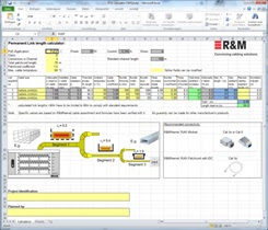
R&M’s PoE calculator with individual entry of all relevant parameters for simulating the expected cable temperatures and the resulting maximum permanent link lengths